Batteries are amazing. Batteries are horrible. Batteries are a necessary evil in today’s world of portable everything. If you’re reading this sentence, even if it’s not on a mobile device, somewhere there is a battery involved. They’re that ubiquitous. There’s another thing batteries are: Expensive! And at $350 each for a specialized battery, [Linus] of Linus Tech Tipsdecided to take battery repair into his own hands.
Rather than do a quick how-to video about putting new cells in an old enclosure, [Linus] does a deep dive into the equipment, skills, and safety measures needed when dealing with Lithium Ion cells. And if you watch the video through, you’ll even get to see those safety measures put to good use!
The real meat of the video comes toward the end however, with its explanation of the different Battery Management Systems (BMS), and a discussion of the difficulty of doing battery repair correctly and safely. Lastly, the video covers something a bit more sinister: Batteries that are made to resist being repaired with new cells; DRM for batteries, so to speak.
Lithium-Sulphur batteries have been on the cusp of commercial availability for a little while now, but nothing much has hit the shelves as of yet. There are still issues with lifetime due to cell degradation, and news about developments seems to be drying up a little. Not to worry, because MIT have come along with a new battery technology using some of the most available and cheap materials found on this planet of ours. The Aluminium-Sulphur battery developed has very promising characteristics for use with static and automotive applications, specifically its scalability and its incredible charge/discharge performance.
The cell is based upon electrodes constructed from aluminium metal and sulphur, with a electrolyte of molten catenated chloro-aluminate salts. With an operating temperature of around 100 degrees Celsius, you’re not going to want this in a mobile phone anytime soon, but that’s not the goal. The goal is the smoothing out of renewable energy sources, and localised electricity grid balancing. A major use case would be the mass charging of battery electric vehicles. As the number of charge points increases at any given location, so does the peak current needed from the grid. Aluminium-Sulphur batteries are touted to offer the solution to ease this, with their high peak discharge current capability enabling a much higher peak power delivery at the point of use.
Right now many of us have household solar installations utilising LiFePo battery technology, with the sheer cost of the battery units limiting the amount of capacity that is installed. Aluminium-Sulphur batteries could easily replace them at a fraction of the cost. With a cost-per-cell less than one-sixth that of Lithium Ion, and construction from extremely common materials, this might be just the technology to disconnect us from the global lithium and cobalt supply chains and enable many more people to generate and make use of electricity in our own homes, after all, the sun doesn’t shine all day.
Need some kind of battery for a project? You can always find a few Lithium-Ion (LiIon) batteries around! They’re in our phones, laptops, and a myriad other battery-powered things of all forms – as hackers, we will find ourselves working with them more and more. Lithium-Ion batteries are unmatched when it comes to energy capacity, ease of charging, and all the shapes and sizes you can get one in.
There’s also misconceptions about these batteries – bad advice floating around, fearmongering videos of devices ablaze, as well as mundane lack of understanding. Today, I’d like to provide a general overview of how to treat your LiIon batteries properly, making sure they serve you well long-term.
What’s A Battery? A Malleable Pile Of Cells
Lithium-Ion batteries are our friends. Now, there can’t be a proper friendship if you two don’t understand each other. Lithium-Ion batteries are tailored for human needs by the factory that produced them. As for us hackers, we’ll want to learn some things.
First thing to learn – a single LiIon “unit” is called a cell. An average laptop contains three or six Li-Ion cells, a phone will have one, a tablet will have from one to three. What we refer to as “battery” is typically one or multiple cells, together with protection circuitry, casing and a separate connector – most of the time all three of these, but not always. The typical voltage is 3.6 V or 3.7 V, with maximum voltage being 4.2 V – these are chemistry-defined, the same for most kinds of cells and almost always written on the cell.
In multiple-cell batteries, the cells are arranged into a mixture of parallel and series arrangements, called a ‘configuration’. For instance, a typical 6-cell laptop battery could be described as a “3s2p” configuration, meaning “three sections in series, in which each section consists of two cells in parallel”. The voltage of such a battery is typically described as one of the battery voltages multiplied by number of series stages; a 3sXp battery voltage could be labelled as 10.8 V, 11.1 V, or 12.6 V.
Parallel cells can be functionally treated as a larger-capacity cell – for instance, if you have two 1000 mAh cells and you need 2000 mAh capacity, you can connect the two cells in parallel and get exactly what you need. Make sure not to parallel cells of significantly different capacity – then, one of those will take more charging current than it perhaps should. This arrangement has one problem: if one of the cells fails internally and starts self-discharging, it brings all the other parallel-connected healthy cells down as well. You might have encountered this failure mode if you have ever disassembled a dead laptop battery.
Shapes And Sizes, All The Same
There’s different physical form-factors for cells – cylindrical, pouch cells and prismatic. 18650 is the most popular cylindrical cell format, where 18 stands for diameter and 65 stands for length (in millimeters). These kind of cells, you’ll typically see in laptop and powertool batteries, electric transportation devices of all kinds.
Pouch and prismatic cells are typically rectangular, with exceptions like cylinder-shaped cells in disposable vapes. These, you’ll see in phones, thinner laptops, tablets, and in general all kinds of handheld devices. I’ll refer to rectangular form-factor cells as “pouch cells” interchangeably.
You’ll often see the term “LiPo” being used online when talking i.e. copter batteries, or just some pouch cells. LiPo technology is a subset of LiIon technology, typically indeed packaged into pouch cells, and is the same as LiIon for the purposes of this article. LiFePO4 is also a subtype of LiIon, it differs by some important aspects like voltages, but most of this article will apply still.
No matter which kind of LiIon cells you’re using, whether a 18650, some “LiPo” single-cell pack, or a pouch cell you took out of a dead smartphone, the electronic components required generally stay the same – mostly thanks to voltages involved being the same. For instance, if you have an ESP32 board with a JST-PH 2-pin input for a battery, it’ll function whether you have a 18650 in a holder with soldered wires, or a pouch cell you got from Adafruit. It isn’t arcane magic – you only have a few rules to follow. Here’s everything you’d ever want to know.
Bring Your Multimeter Out
LiIon batteries don’t like being overdischarged; as a rule, you don’t want to get a LiIon battery below 2.5 V – 3.0 V, depending on how much current you’re trying to draw at that voltage. Below a certain voltage, LiIon batteries suffer irreversible changes and lose their capacity. 3.0 V is my personal threshold, making sure my batteries last even longer. No, it’s not a requirement that you add an ADC to your payload – just make sure your battery has a protection circuit; those typically are set to protect from 2.5 V overdischarge, and you can get 3.0 V ones too if you’d like.
If you go gently on discharge, your battery will live longer. This is why your phone’s “0% battery” isn’t the real 0% of the battery’s capacity – there’s usually some juice left still, but using it up would have the battery capacity take a hit long-term. This is also why some laptops have a BIOS-accessible 80% battery charge level limitation for the purpose of extending the pack’s life expectancy – you trade some operational capacity for that, but it’s a worthwhile tradeoff to consider.
TP4056 is a hacker’s best friend when it comes to LiIon batteries – and now it comes in “non-compliant USB-C” flavor!
LiIon batteries want to be charged properly. You’ll see CC/CV mentioned – that refers to “constant current/constant voltage”, where first the battery is fed a constant current with the cell increasing its voltage as it charges, and once its voltage reaches some threshold, the charging mode is switched to keep the charging voltage somewhat constant and decrease the current over time instead. This two-stage charging process requires a charging IC – thankfully, those are omnipresent. If you have a device accepting a LiIon battery, it likely has an onboard charger; for your own devices, chargers are easy to find as modules.
When working with a small cells under 1000 mAh, you’ll want to ensure your charging current is half of the battery capacity number, or even less – so, for a 1000 mAh cell, it’d be 0.5 A or lower. For instance, the everpresent TP4056 modules are set up for 1 A current. Say, you tried to charge a 100 mAh battery with that – this is one of the rare cases where the cell might get fiercely dissatisfied with your treatment. Thankfully, for the blue “TP4056” modules, swapping a resistor is all it takes – and TP4056 boards often include a protection circuit as well!
Protection And Monitoring
Remember – LiIon cells can put a lot of current into whatever you connect to their terminals. When working with unprotected cells, it’s important that you don’t short them by accident. For instance, if you’d like to repair a powerbank, unsolder the negative terminal first – just like with car batteries. This will decrease the chances of you shorting the positive pin to to ground with your soldering iron – that would trip the protection circuit, cause a small spark, and possibly make your battery lose some of its capacity. This is one more reason why you have a protection circuit – these trip on overcurrent events.
The kind of mistake you quickly learn to avoid
Let’s recap: with a single-cell (or single-stage) battery, you’ll want a protection circuit, and there’ll be a charger somewhere in the picture. For LiIon packs where multiple cells are connected in series, you’ll want a protection circuit that’s wired into between-cell connections, for proper overdischarge monitoring – and you’ll also want some form of balancing wired into these, making sure that individual sections of the battery don’t overcharge. This protection+balancing circuitry combination is often referred to as “BMS” (battery management system).
If you end up having quite a few unused batteries or cells lying around, there’s something you could improve upon. It’s been found that you shouldn’t store your batteries long-term at 100% charge, as that might cause capacity loss – 50-60% charge is a better level for storage. So, if you want to put your cells on a shelf for a few months or more, it’s best if you get them to 3.8 V-3.6 V first. Not that full charge storage is going to kill your battery – can’t deny, I’ve been storing most of my cells fully charged and it hasn’t been a dealbreaker so far. This is a lot more of a concern for LiPo pouch batteries than LiIon cells.
Mechanical Manipulations
Not that bending a LiIon battery is disastrous – still, don’t do this to cells you care about.
If you ever need to use blunt force to remove a glued-in cell, use non-sharp plastic tools instead of metal ones – and try to find a different way first. Let’s say, you want to free a pouch cell from an old tablet. First, try to squirt liberal amounts of isopropyl under the battery and let it soften, and twist the cell instead of bending it – you might find that you don’t need any tools at all. If you do need to pry the cell with something, use a cut up old credit card. Heating (i.e. hairdryer) is generally advised against.
One thing I strongly recommend you avoid is puncturing a puffed up pouch cell. Of course, sometimes a puncture happens by accident when refurbishing things, and you’re going to be fine if you move away from the cell for a bit, but don’t go around poking holes in spicy pillows for fun.
For 18650 (cylindrical) cells, it’s harder to puncture them, but still possible. One of these cases is taking a laptop battery apart, cutting through the battery case plastic with sharp metal tools – beware! The case is the negative terminal, so if you nick the shrink wrap, don’t make contact with the positive tip. However, if your 18650 plastic covering is missing or torn, that’s fine – it’s just a special kind of heatshrink, you can buy it for cheap and put it on the cell with hot air.
Such holders are indispensable if you want to use 18650 cells
If you want to use 18650s in your own creations, you’re best off stocking up on holders, or printing some. The second best thing is spot welding metal strips onto them – some shops will do that for you, – and soldering wires to these. Soldering directly to 18650 cells is a tricky topic. The consensus is that it can be done, but it’s best if you don’t.
Applying heat to 18650 cell casing is best done in small amounts – as such, using a higher-power soldering iron for short amounts of time is probably the safest way you can do it. Perhaps one of your friends or a nearby hackerspace has a spot welder that you can use instead – or you can build your own?
Storing cells and batteries long-term isn’t rocket science – a free shelf will do. Make sure that they’re not mechanically at risk, aka they won’t fall, nothing heavy/sharp is on them, yadda yadda. For pouch cells without protection circuits, you’ll want to wrap the exposed terminals in something like kapton tape while they’re being stored, and put them somehwere fire-safe just in case. For 18650s, there’s cheap plastic cases you can store them in. Ammo boxes might be tempting, but make sure the metal doesn’t short the cells out as they rattle inside.
Be Picky When Making Friends
As hackers, we can get LiIon cells from a myriad of different sources. This is wonderful, since our projects come in all shapes and sizes – some will be fine with 18650, some can be powered by a smartphone battery or an ultrabook-scavenged flat cell, some are small enough that perhaps a vape battery will be a better bet.
Corrosion on the protection circuit or its terminals? Bin it.
Not all of these cells will be good for you, however – there’s some easy indicators that the cell is subpar and perhaps internally damaged, and these signs, you should watch out for. I’ll give you an acronym – L.U.S.H., which stands for “Lacerated, Undervolted, Subpar, Heated”.
Is the silver wrapper of your pouch cell cut? Is your 18650 dented on its side? Did you mishandle an RC car LiPo pack and now it’s squished together in the way it wasn’t before? If so, recycle it rather than reusing it. It’s okay to have a bit of a dent on your 18650’s negative terminal as you use tin snips to get rid of spot-welded strip remains. Other than that, there’s typically not a lot of mechanical leeway between the side wall of the cell and its internal layers of electrodes, and squeezing these layers together is a possible failure point.
If the cell is lower than 2.5 V, bin it. In case your cell has a protection circuit and that circuit’s output is at 0 V, you might want to measure before the protection circuit, directly on the cell’s contacts – typically gently cutting through kapton or plastic tape where necessary, perhaps using sewing needles held against your multimeter probes. Again, if below 2.5 V, bin it – and consider keeping the protection circuit, it might prove useful later! Also, be reasonable – if you’ve disassembled a laptop battery, where two sections are at 3.5 V and one is at 3 V, you better bin the latter.
Bin this one, too.
Capacity loss means the cell has been damaged, and you don’t want to be using a damaged LiIon cell. For instance laptop battery makers use indicators of cell damage (overdischarge, overcharge and overheating) as a trigger to shut the battery controller down and brick the entire battery – and it makes sense, since they don’t want to have the liability. Even then, overall severe capacity loss isn’t usually considered a trigger for such protection. That said – if a battery has subpar capacity for its size or rating, bin it.
When charging the battery for the first time after it’s freed up from its previous host, make sure it doesn’t heat up noticeably – if it does, bin it. After charging, measure the voltage and write it down. It’s going to gradually decrease after you stop charging, but it shouldn’t drop too much. If it drops more than 0.3 V from where it was after you stopped charging, or just keeps dropping and dropping over the week, bin it – high levels of self-discharge typically go hand in hand with capacity loss.
Wait, What About Those Fires?
The risks of fire with LiIon cell batteries in typical hacker usecases are negligible. After all, we typically have thousands of LiIon cells in our general vicinity – consider all the phones, laptops, electric cars and the like, and they work wonders long-term across thousands of cycles. Typical LiIon fires happen because of mechanical damage to the cell, severe neglect of its electrical requirements, and rarely, mis-manufacturing. Having learned to treat your cells well and bin them when called for, you’re well-equipped to avoid battery fires ever happening. Want to learn more about LiIon battery fire safety specifically? Our colleague has talked about that in depth.
When you need to dispose of a dead or subpar LiIon battery, are you understandably worried about its terminals getting shorted or the cell getting punctured after you bin it? Good news – a fully discharged battery is completely safe from any accidents, no longer having internal energy for combustion.
How to fully discharge a cell? First, you could short the cell’s terminals with something like a 10 K through-hole resistor and leave it to discharge fully. Make sure to connect to the cell and not the protection circuit output! Another way I’ve seen people do is put the cell (or an entire pack) in saltwater and hold it there for a while – best done outdoors in an open container. This might sound a bit wack, but there’s scientific research aplenty! [Ed note: sounds wack! I just use a resistor.]
Go On, LiIon!
We haven’t always been well-equipped to handle LiIon batteries. It used to be that bargain bin devices used two diodes from a 5 V input to “charge” the battery – resulting in puffy and dissatisfied pouch cells. Nowadays, you’ll see hackers and makers equipping their devices with LiIon batteries left and right, protection boards and chargers are everpresent, and the skills ought to be ubiquitous too. Never stop learning, and you’ll always be equipped to make your projects more portable, failproof and trustworthy.
Next time, I’d like to talk about specifics – I want to give you a hacker-friendly cookbook with LiIon battery electronics examples that are easily repeatable at home. Until then – solder a JST-PH lead onto a smartphone cell and plug it into that ESP32 board you bought, see what that lets you achieve!
In the first article, I’ve given you an overview of Lithium-Ion batteries and cells as building blocks for our projects, and described how hackers should treat their Lithium-Ion cells. But what if you don’t have any LiIon cells yet? Where do you get LiIon cells for your project?
Taking laptop batteries apart, whether the regular 18650 or the modern pouch cell-based ones, remains a good avenue – many hackers take this road and the topic is extensively covered by a number of people. However, a 18650 cell might not fit your project size-wise, and thin batteries haven’t quite flooded the market yet. Let’s see what your options are beyond laptops.
First underappreciated source of LiIon cells, specifically pouch cells, are smartphone batteries. Of course, we’ve all seen a phone battery die earlier than the phone did, and in many modern phones, the cell is glued-in and harder to extract. However, shopping for smartphone batteries in your local stores is still worthwhile if you need a small cell to power your device.
For instance, user-replaceable batteries are still manufactured and sold for numpad phones from manufacturers like Nokia, with cells typically around 1000 mAh, more than enough for a small ESP32 or Pi Pico project that spends lots of time asleep. If you’d like to make your device repeatable by others and make battery sourcing simple, perhaps work around LiIon shipping restrictions, or if you’re a garage startup itching to get a small prototype batch out of the door, smartphone batteries are a good bet.
Even more, there’s not much preventing you from putting the same contacts used by phones onto your PCB. You can source these contacts from online repair shops, LCSC, Aliexpress and probably more. With a smartphone cell, you get a protection circuit, usually a built-in thermistor and often a one-wire or I2C fuel gauge. Most importantly, you get a battery with an active supply chain, which means you can design it into your project mechanically and electrically, and not fear a redesign a few months in when all local stock of a very specific cell suddenly runs out. One small thing to keep in mind – while older Nokia batteries have a third pin, it’s not a thermistor pin – instead, it’s a fixed-value cell identification resistor.
We’ve seen this done with iPhone batteries, and we’ve also seen things like makeshift pin header-based holders for smartphone cells. I first encountered it when I saw pictures of a Chinese radio using Nokia format batteries, and I’ve been designing them into small-scale stuff ever since. You don’t have to look for “genuine” cells, third-party cells with good reviews are a decent source and tend to provide more value per dollar, but bottom-of-the-barrel cells are likely to disappoint.
Vaping has helped make LiIon cells a bit more accessible. First off, disposable vapes provide us with small cells that are nicely reusable – remember to use protection. However, vape shops are also a decent source of high-current-capable 18650 cells, and if you’re a hobbyist designing a device with an 18650 holder in it, you don’t have to worry about battery shipping restrictions unfairly impacting small-scale producers when you can ask your recipient to go to a vape shop and buy a 18650 for a modest markup.
There are also specialized stores that sell LiIon cells and batteries, 18650 and pouch alike, with good prices and inexpensive ground shipping. Quad and other remote-controlled vehicles eat them up, so a shop like Hobby King often has good deals. In Europe, Nkon is one of the go-tos, and I’ve had great success getting 3.5 Ah cells from there with prices comparable to Aliexpress fake “6.5 Ah cell” listings. Speaking of that, I can’t say I recommend Aliexpress – to this day, they seem to need to resort for tricks when airmailing you cells, which sometimes still get randomly seized by customs screening, and cells of subpar quality have a non-negligible market share there.
Mind The Mechanics
Once you got hold of some cells, how do you connect them into your circuit? If they’re 18650s, it’s good to have a holder – Thingiverse has no shortage of printable ones, and commercially made holders tend to be less frustrating to use. Leaf contact holders are better than spring-based ones when it comes to higher-current applications; otherwise, you might never notice a difference. In a pinch, if you have four disk magnets, you can clamp two wires between two magnet and snap them onto your 18650s for a holder – I’ve done that for a hackathon once, when we badly needed to power a Raspberry Pi 3 inside a wearable device and there was no a suitable powerbank around.
With a pouch cell, if it has wires that terminate in a plug, it’s good to have a receptacle for it – desolder it from the original device if needed. Otherwise, you can fashion a plug out of pin headers, even if it’s going to be non-polarized – you’ll want to add your own polarity mechanism, i.e. color-coding. Remember, female header on the power source, male header on the power input – shorting the battery is worse than shorting a non-connected power input by accident.
If your pouch cell doesn’t have a connector and just has tabs, you’ll want to solder to those tabs – but a good practice is that you clamp a crocodile clip between the solder point and the battery before soldering, for heatsinking purposes. These tabs are wired up directly to the polymer layers inside the cell, and overheating that might shorten the battery life.
You’ll also want to make sure that pouch cells are not at risk of being punctured or squished, and that this doesn’t happen if the cell starts to puff up, either. This means not gluing it to the bottom of your board if you also have through-hole pins sticking out on that side, for a start. Having a 3D-printed holder with at least one wall being bendy and thin (if not open) will be helpful – and make sure that the cell doesn’t end up being stuck inside this holder in the not-unlikely case that it decides to puff up. Smartphone batteries of the swappable kind tend to be a bit sturdier, but you still would benefit from extra mechanical protection.
A good connector for LiIon pouch cells is a two-pin JST-PH – it’s the one you will see most often on random boards out in the wild, and therefore the one that it makes sense you stock up on connectors and cables for. When it comes to the PCB side connectors, you should get the SMD version, JST part number being S2B-PH-SM4-TB and alternatives searchable using “1x2P PH 2mm”. Sadly, the through-hole version of this connector is flimsy, lacking shell mounting pins – the metal pins break off relatively quickly, whereas the SMD version is quite sturdy and stays on the board.
As you get into the groove of adding battery power to your projects, it will help a lot if you stock up on some JST-PH leads in advance, from places like Adafruit, Aliexpress or other stores – I got a 50-pack from the Lilygo store. Crimping your own, while technically possible, might result in wires that pull out of the crimp easily, which is a giant pain and tends to happen at the most inopportune moment. We’ve covered the subject of crimping extensively; the gist is, if you don’t have access to a proper crimping tool, it’s way better to buy a bouquet of pre-crimped wires. When unplugging a JST-PH connector, it’s best to grab it by its wings with flush cutters or tin snips.
Careful – even though JST-PH connectors are used on boards from a large variety of different hobbyist manufacturers, there are two different pinouts for JST-PH 2-pin battery plugs. Places like Adafruit, Sparkfun, HobbyKing and others use a pinout where the positive (red) is pin 1 and negative (black) is pin 2, whereas many Chinese sellers have it the other way around – negative being pin 1 and positive being pin 2. This divide, thankfully, doesn’t extend to microcontroller boards – Wemos and Lolin boards seem to use the same pinout as Adafruit and Sparkfun.
Plugging a battery in reverse is basically guaranteed to kill your board – to be exact, at least its power management components. With JST-PH 2-pin, this means you should always check your pinouts. If you design your own board, you should place pinout markings on the silkscreen next to the connector – a practice that more PCB designers ought to adhere to when they add JST-PH battery connectors to their boards. Thankfully, you can easily rewire JST-PH plugs to whichever standard you desire to stick with – and take care not to short-circuit the cell as you pull its contacts out of their shell while rewiring the plug.
Taking Flight
If you carry a battery-powered DIY device, going to an airport might sound intimidating, yet it’s more viable than it might sound – if you want to take your device with you as you embark on a flight, you can. Keep in mind – LiIon cells and devices with LiIon batteries in them have to be in your carry-on, and they’ll have to go through the security scanners just like your laptop and phone. Making your device more presentable to some extent will help, and keeping the batteries separate from the device is a great idea if you want your airport security queue experience to be seamless. Again, both pouch cells and 18650s are best stored in some kind of hard case when transporting them. With a bit of presentability and precautions combined, your creations can travel with you.
Next time, let’s talk about the electronics nitty-gritty – charging cells in 1s configuration, converting LiIon voltage to more friendly 3.3 V, protection and power paths, with ready-to-use examples you can put on your boards.
By now, we’ve gone through LiIon handling basics and mechanics. When it comes to designing your circuit around a LiIon battery, I believe you could benefit from a cookbook with direct suggestions, too. Here, I’d like to give you a collection of LiIon recipes that worked well for me over the years.
I will be talking about single-series (1sXp) cell configurations, for a simple reason – multiple-series configurations are not something I consider myself as having worked extensively with. The single-series configurations alone will result in a fairly extensive writeup, but for those savvy in LiIon handling, I invite you to share your tips, tricks and observations in the comment section – last time, we had a fair few interesting points brought up!
The Friendly Neighborhood Charger
There’s a whole bunch of ways to charge the cells you’ve just added to your device – a wide variety of charger ICs and other solutions are at your disposal. I’d like to focus on one specific module that I believe it’s important you know more about.
You likely have seen the blue TP4056 boards around – they’re cheap and you’re one Aliexpress order away from owning a bunch, with a dozen boards going for only a few bucks. The TP4056 is a LiIon charger IC able to top up your cells at rate of up to 1 A. Many TP4056 boards have a protection circuit built in, which means that such a board can protect your LiIon cell from the external world, too. This board itself can be treated as a module; for over half a decade now, the PCB footprint has stayed the same, to the point where you can add a TP4056 board footprint onto your own PCBs if you need LiIon charging and protection. I do that a lot – it’s way easier, and even cheaper, than soldering the TP4056 and all its support components. Here’s a KiCad footprint if you’d like to do that too.
This is a linear charger IC – if you want 1 A out, you need 1 A in, and the input-output voltage difference multiplied by current is converted into heat. Thankfully, the TP4056 modules are built to handle high temperatures reasonably well, and you can add a heatsink if you want. Maximum charging current is set by a resistor between ground and one of the pins, default resistor being 1.2 kΩ resulting in 1 A current; for low-capacity cells, you can replace it with a 10 kΩ resistor to set a 130 mA limit, and you can find tables online for intermediate values.
There’s some cool things about the TP4056 IC that most people don’t know about if they’re using the modules as-is. The IC’s CE pin is hardwired to 5 V VIN, but if you lift that pin, you can use it to disable and enable charging with a logic level input from your MCU. You can monitor the charging current by connecting your MCU’s ADC to the PROG pin – the same pin used for the current setting resistor. There’s also a thermistor pin, typically wired to ground, but adaptable for a wide range of thermistors using a resistor divider, whether it’s the thermistor attached to your pouch cell or one you added externally to your 18650 holder.
There’s problems with the TP4056 too – it’s a fairly simple IC. Efficiency isn’t an imperative where wall power is available, but the TP4056 does waste a decent bit of power as heat. A switching charger-based module avoids that, and often also lets you charge at higher currents if ever required. Connecting a cell in reverse kills the chip, and the protection circuit too – this mistake is easy to make, I’ve done that aplenty, and this is why you need spares. If you reverse the cell contacts, throw the board out – don’t charge your cells with a faulty IC.
Also, given the TP4056’s popularity, copies of this IC are manufactured by multiple different chip vendors in China, and I’ve observed that some of these copy ICs break more easily than others, for instance, no longer charging your cells – again, keep spares. The TP4056 also doesn’t provide charging timers like other, more modern ICs do – a subject we touched upon in the comment section of the first article.
All in all, these modules are powerful and fairly universal. It’s even safe to use them to charge 4.3 V cells, as due to the CC/CV operation, the cell simply won’t charge to its full capacity – prolonging your cell’s life as a side effect. When you need to go beyond such modules, there’s a myriad of ICs you can make use of – smaller linear chargers, switching chargers, chargers with built-in powerpath and/or DC-DC regulator features, and a trove of ICs that do LiIon charging as a side effect. The world of LiIon charger ICs is huge and there’s way more to it than the TP4056, but the TP4056 is a wonderful starting point.
The Protection Circuit You Will See Everywhere
Just like with charging ICs, there’s many designs out there, and there’s one you should know about – the DW01 and 8205A combination. It’s so ubiquitous that at least one of your store-bought devices likely contains it, and the TP4056 modules come with this combo too. The DW01 is an IC that monitors the voltage of your cell and the current going to and from it, and the 8205A is two N-FETs in a single package, helping with the actual “connect-disconnect the battery” part. There’s no additional current sensing resistor – instead, the DW01 monitors voltage across the 8205A junction. In other words, the same FETs used to cut the cell from the outside world in case of failure, are used as current sensing resistors. This design is cheap, prevalent, and works wonders.
The DW01 protects from overcurrent, overdischarge and overcharge – the first two happen relatively often in hobby projects, and that last one’s handy if your charger ever goes rogue. If something wrong happens, it interrupts the connection between the cell’s negative terminal and GND of your circuit, in other words, it does low-side switching – for a simple reason, FETs that interrupt GND are cheaper and have lower resistance. We’ve also seen some hacks done with this chip – for instance, we’ve covered research from a hacker who figured out that the DW01 can be used as a soft power switch for your circuit – in a way that doesn’t compromise on safety. You only need to connect a GPIO pin of your MCU to the DW01, preferably through a diode – this comment describes an approach that seems pretty failure-resistant to me.
When you first connect a LiIon cell to the DW01+8205A combination, sometimes it will enable its output, but sometimes it won’t. For instance, if you have a holder for 18650s and a protection circuit connected to it, it’s a 50/50 chance that your circuit will power up once you insert the battery. The solution is simple – either connect a charger externally, or short-circuit the OUT- and B- with something metal (I often add an external button), but it’s annoying to deal with. Just like TP4056, the DW01+8205A combo dies if you connect the battery in reverse. Also, the DW01 is internally wired for 2.5 V overdischarge cutoff, which technically isn’t changeable. If you don’t have a separate software-controlled cutoff, the FS312 is a pin-compatible DW01 replacement with 3.0 V overdischarge point, helping you prolong your cell’s life.
You can buy a batch of ready-to-go protection circuit modules, or just use the protection circuit laid out on the TP4056 module PCB. You can also accumulate a decent stock of protection circuits by taking them out of single-cell batteries whenever the cell puffs up or dies – take caution not to puncture the cell while you do it, please.
All The Ways To Get 3.3 V
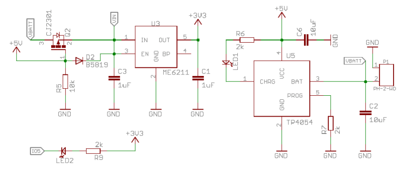
For a 4.2 V LiIon cell, the useful voltage range is 4.1 V to 3.0 V – a cell at 4.2 V quickly drops to 4.1 V when you draw power from it, and at 3.0 V or lower, the cell’s internal resistance typically rises quickly enough that you will no longer get much useful current out of your cell. If you want to get to 1.8 V or 2.5 V, that is not a problem, and if you want to get to 5 V, you’ll use a boost regulator of some sort. However, most of our chips still run at 3.3 V – let’s see what our options are here.
When it comes to LiIon range to 3.3 V regulation, linear regulators closely trail switching regulators in terms of efficiency, often have lower quiescent (no-load) current if you seek low-power operation, and lower noise if you want to do analog stuff. That said, your regular 1117 won’t do – it’s an old and inefficient design, and the 1117-33 starts grinding its gears at about 4.1 V. Instead, use pin-compatible, low dropout voltage replacements like AP2111, AP2114 and BL9110, or AP2112, MIC5219, MCP1700 and ME6211 if you’re okay with SOT23 stuff. All of these are linear regulators comfortable providing 3.3 V with input down to 3.5 V and sometimes even 3.4 V, if you’d like to power something like an ESP32. It’s hard to deny the simplicity of using a linear regulator – one chip and a few caps is all it takes.
If you want 500 mA to 1000mA or even more current on an ongoing basis, a switching regulator will be your best friend. My personal favourite is PAM2306 – this regulator is used on the Raspberry Pi Zero, it’s very cheap and accessible, and even has two separate output rails. Given its capability to do 100% duty cycle operation, it can extract a lot of juice out of your cells, often desirable for higher-power projects where runtime matters. And hey, if you got Pi Zero with a dead CPU, you won’t go wrong snipping a part of the PCB off and soldering some wires to it. When designing your own board, use datasheet recommendations for inductor parameters if the whole “picking the right inductor” business has you confused.
So, the PAM2306 is the regulator on the Pi Zero, and it’s also LiIon-friendly? Yep, you can power a Pi Zero directly from a LiIon battery, as all the onboard circuitry works down to 3.3 V on the “5 V” pins. I’ve tested it extensively in my own devices, and it even works with the Pi Zero 2 W. Combined with this powerpath and a charger, you have a complete “battery-powered Linux” package, with all the oomph that a Raspberry Pi provides – at cost of only a handful of components. One problem to watch out for is that MicroUSB port VBUS will have battery voltage – in other words, you’re best off filling the MicroUSB ports with hot glue just in case someone plugs a MicroUSB PSU there, and tapping the USB data testpoints for USB connectivity.
A Power Path To Join Them All
Now, you’ve got charging, and you got your 3.3 V. There’s one problem that I ought to remind you about – while you’re charging the battery, you can’t draw current from it, as the charger relies on current measurements to control charging; if you confuse the charger with an extra load, you risk overcharging the battery. Fortunately, since you have a charger plugged in, you must have 5 V accessible. It’d be cool if you could power your devices from that 5 V source when it’s present, and use the battery when it’s not! We typically use diodes for such power decisions, but that’d cause extra voltage drop and power losses when operating from the battery. Thankfully, there’s a simple three-component circuit that works way better.
In this power path circuit, a P-FET takes role of one of the diodes, with a resistor opening the FET while the charger’s not present. The P-FET doesn’t have a voltage drop, but instead has resistance in fractions of an ohm, so you avoid losses when the charger’s not plugged in. Once the charger is connected, the FET closes, and the charger powers your circuit through the diode instead. You need a logic-level P-FET – IRLML6401, CJ2305, DMG2301LK or HX2301A would fit, and there’s thousand others that will work. As for a diode, a default Schottky like 1N5819 (SS14 for SMD) will do. It’s a ubiquitous circuit and deserves its place in circuit toolboxes.
You can buy shields and modules that contain all of these parts and sometimes more, on a single board. You can also buy ICs that contain all or some of the parts of this circuit, often improved upon, and not worry about the specifics. These ICs tend to be more expensive, however, and way more subject to chip shortages than the individual component-based solution. Plus, when issues arise, understanding of inner workings helps a whole lot. Thus, it’s important that the basics are demystified for you, and you don’t feel forced into reusing powerbank boards next time you want to make a device of yours portable.
Be on the lookout on what other boards are doing. Often, you’ll see the charger + regulator + powerpath circuit described above, especially when it comes to cheaper boards with chips like the ESP32. Other times, you’ll see more involved power management solutions, like powerbank chips or PMICs. Sometimes they’re going to work way better than the simple circuit, sometimes it’s the opposite. For instance, some TTGO battery-powered boards use powerbank chips and overcomplicate the circuit, resulting in weird behaviour and malfunctions. A different TTGO board, on the other hand, uses a PMIC that’s way more suited for such boards, which results in flawless operation and even granular power management control for the user.
Hack Portable Devices Like You Couldn’t Before
Now you know what it takes to add a LiIon battery input connector to your project, and the secrets behind the boards that come with one already. It’s a feeling like no other, taking a microcontroller project with you on a walk as you test out a concept of yours. I hope I got you a bit closer to experiencing it.
Next time, I’d like to talk about batteries with multiple cells in series – BMSes, balancing and charging LiIon packs from different sources. That, however, will take a good amount of time for me to prepare, as I’d like to finish a few related projects first, and I recommend you check this coverage of ours out if you’d like to learn about that. In the meantime, I wish you luck in building your battery-powered projects!
Lithium-ion and lithium-polymer rechargeable batteries have given us previously impossible heights of electronics power and miniaturization, but there’s a downside they have brought along with them. When a battery pack has to contain electronics for balancing cells, it’s very easy for a manufacturer to include extra functions such as locking down the battery. Repair a battery, replace cells, or use a third-party battery, and it won’t work. [Zolly] has this with a DJI Mavic Mini pack, and shares with us a method for bypassing it.
The pack talks to the multi-rotor with a serial line, and the hack involves interrupting that line at the opportune moment to stop it telling its host that things are amiss. Which is a good start — but we can’t help hacing some misgivings around the rest of the work. Disconnecting the balance line between the two cells and fooling the Battery Management System (BMS) with a resistive divider seems to us like a recipe of disaster, as does bypassing the protection MOSFETs with a piece of wire. It may work, and in theory the cells can be charged safely with an external balance charger, but we’re not sure we’d like to have a pack thus modified lying around the shop.
It does serve as a reminder that BMS boards can sometimes infuriatingly lock their owners out. We once encountered this with a second-generation iBook battery that came back to life after a BMS reset, but it’s still not something to go into unwarily. Read our guide to battery packs and BMS boards to know more.
Lithium batteries have, nearly single-handedly, ushered in the era of the electric car, as well as battery energy storage of grid power and plenty of other technological advances not possible with older battery chemistries. There’s just one major downside: these lithium cells can be extremely finicky. If you’re adding one to your own project you’ll have to be extremely careful to treat them exactly how they are designed to be treated using something like this boilerplate battery protection circuit created by [DIY GUY Chris].
The circuit is based around the TP4056 integrated circuit, which handles the charging of a single lithium cell — in this design using supplied power from a USB port. The circuit is able to charge a cell based on the cell’s current charge state, temperature, and a model of the cell. It’s also paired with a DW01A chip which protects the cell from various undesirable conditions such as over-current, overcharge, and over-voltage.
The best thing about this design isn’t the design itself, but that [DIY GUY Chris] built the circuit schematic specifically to be easily copied into PCB designs for other projects, which means that lithium batteries can more easily be integrated directly into his other builds. Be sure to check out our primer on how to deal with lithium batteries before trying one of your own designs, though.


 Pouch and prismatic cells are typically rectangular, with exceptions like cylinder-shaped cells
  LiIon batteries don’t like being overdischarged; as a rule, you don’t want to get a LiIon battery below 2.5 V – 3.0 V, depending on how much current you’re trying to draw at that voltage. Below a certain voltage, LiIon batteries suffer irreversible changes and lose their capacity. 3.0 V is my personal threshold, making sure my batteries last even longer. No, it’s not a requirement that you add an ADC to your payload – just make sure your battery has a protection circuit; those typically are set to protect from 2.5 V overdischarge, and you can get 3.0 V ones too if you’d like.


 When you need to dispose of a dead or subpar LiIon battery, are you understandably worried about its terminals getting shorted or the cell getting punctured after you bin it? Good news – a fully discharged battery is completely safe from any accidents, no longer having internal energy for combustion.
 We’ve seen this done
  There are also specialized stores that sell LiIon cells and batteries, 18650 and pouch alike, with good prices and inexpensive ground shipping. Quad and other remote-controlled vehicles eat them up, so a shop like Hobby King often has good deals. In Europe, Nkon is one of the go-tos, and I’ve had great success getting 3.5 Ah cells from there with prices comparable to Aliexpress fake “6.5 Ah cell” listings. Speaking of that, I can’t say I recommend Aliexpress – to this day, they seem to need to resort for tricks when airmailing you cells, which sometimes still get randomly seized by customs screening, and cells of subpar quality have a non-negligible market share there.
 If your pouch cell doesn’t have a connector and just has tabs, you’ll want to solder to those tabs – but a good practice is that you clamp a crocodile clip between the solder point and the battery before soldering, for heatsinking purposes. These tabs are wired up directly to the polymer layers inside the cell, and overheating that might shorten the battery life.
 Careful – even though JST-PH connectors are used on boards from a large variety of different hobbyist manufacturers,
 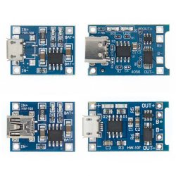 This is a linear charger IC – if you want 1 A out, you need 1 A in, and the input-output voltage difference multiplied by current is converted into heat. Thankfully, the TP4056 modules are built to handle high temperatures reasonably well, and you can add a heatsink if you want. Maximum charging current is set by a resistor between ground and one of the pins, default resistor being 1.2 kΩ resulting in 1 A current; for low-capacity cells, you can replace it with a 10 kΩ resistor to set a 130 mA limit, and you can find tables online for intermediate values.
 There’s problems with the TP4056 too – it’s a fairly simple IC. Efficiency isn’t an imperative where wall power is available, but the TP4056 does waste a decent bit of power as heat. A switching charger-based module avoids that, and often also lets you charge at higher currents if ever required. Connecting a cell in reverse kills the chip, and the protection circuit too – this mistake is easy to make, I’ve done that aplenty, and this is why you need spares. If you reverse the cell contacts, throw the board out – don’t charge your cells with a faulty IC.
 The DW01 protects from overcurrent, overdischarge and overcharge – the first two happen relatively often in hobby projects, and that last one’s handy if your charger ever goes rogue. If something wrong happens, it interrupts the connection between the cell’s negative terminal and GND of your circuit, in other words, it does low-side switching – for a simple reason, FETs that interrupt GND are cheaper and have lower resistance. We’ve also seen some hacks done with this chip – for instance, we’ve covered research from a hacker who figured out that the DW01
 So, the PAM2306 is the regulator on the Pi Zero, and it’s also LiIon-friendly? Yep, you can power a Pi Zero directly from a LiIon battery, as all the onboard circuitry works down to 3.3 V on the “5 V” pins. I’ve tested it extensively in my own devices, and it even works with the Pi Zero 2 W. Combined with this powerpath and a charger, you have a complete “battery-powered Linux” package, with all the oomph that a Raspberry Pi provides – at cost of only a handful of components. One problem to watch out for is that MicroUSB port VBUS will have battery voltage – in other words, you’re best off filling the MicroUSB ports with hot glue just in case someone plugs a MicroUSB PSU there, and tapping the USB data testpoints for USB connectivity.
 Now, you’ve got charging, and you got your 3.3 V. There’s one problem that I ought to remind you about – while you’re charging the battery, you can’t draw current from it, as the charger relies on current measurements to control charging; if you confuse the charger with an extra load, you risk overcharging the battery. Fortunately, since you have a charger plugged in, you must have 5 V accessible. It’d be cool if you could power your devices from that 5 V source when it’s present, and use the battery when it’s not! We typically use diodes for such power decisions, but that’d cause extra voltage drop and power losses when operating from the battery. Thankfully, there’s a simple three-component circuit that works way better.